NoNameBadge
First Ukrainian hardware hackable conference badge
Specifications
The main batch of conference badges will contain an ESP32 board, 10x WS2812 LEDs and a few touch-sensitive buttons. This is enough for entertainment, dealing with badge tasks, and the memory for the conference.
The Badge tasks are something like a Capture the Flag. We want everyone to complete at least 1-2 out of 6 tasks (at the time of publication). To work with the tasks it is enough to have a laptop, a microUSB cable, and putty/screen installed.
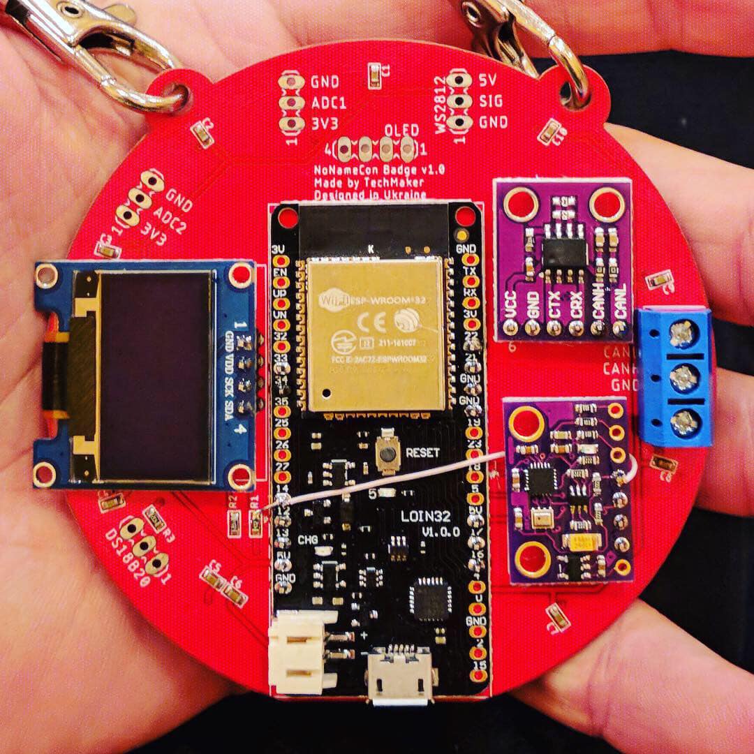
During the conference, visitors will have the opportunity to purchase additional modules and manually roll them into their badge. Among the modules:
1. a CAN transceiver for automotive networks
2. an MPU9050 to calculate the position in space and... weather forecast
The ESP32 architecture allows you to output the desired interfaces (UART, I2C, SPI, CAN, etc.) to any external components. This opens up the ability to connect any compatible peripherals/sensors to the badge.
That is our goal. The Badge is created to give conference participants a complete platform for discovering the world of IoT and Embedded. During 2019, a series of webinars and workshops will be held using the badges under the brands of TechMaker and NoNameCon. The badge should not collect dust on the shelf. Its role is not limited to giving you access to the conference. You get a ticket to the world of development of devices and protecting them against modern threats.

Instructions
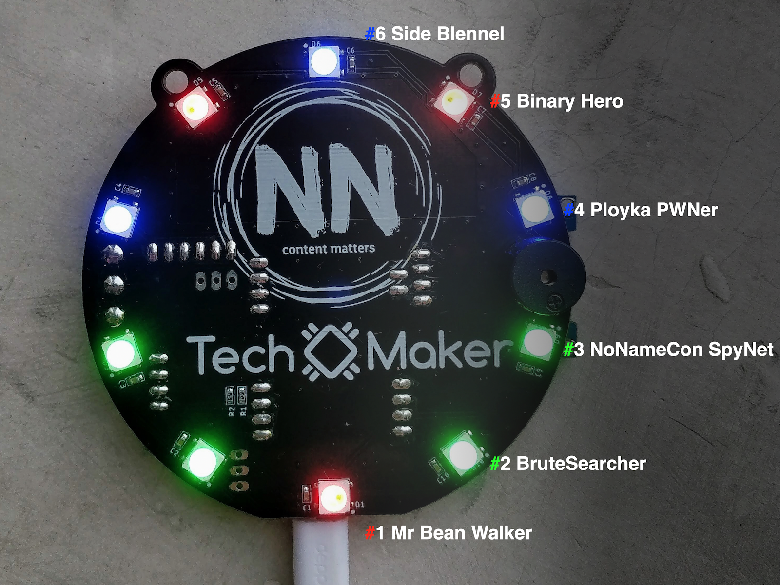
To turn the badge on - connect it to the power bank or USB port of the computer using the micro USB cable. During the first switch-on, all LEDs will be turned off. Solved tasks will light the corresponding LEDs. The 'light state' of the badge will help you find the interlocutors among the conference visitors and share experiences.
A touch on the microcontroller icon will turn on the rainbow. Further touches will light random colors on the LEDs. To return to the original state, press the Reset button or turn off the power and turn it back on again.
The board includes plug-in connectors for connecting modules: an OLED screen, a CANbus transceiver, an accelerometer/gyroscope, and so on. During the conference, you can try to find where to buy them and where to solder them to the badge.
NB: LEDs will not light up when you connect Li-Po to the board connector. This is done intentionally, as during operation they can consume significant current (several amperes).
Your badge contains the firmware with 6 tasks. Names and topics:
- Mr Bean Walker – reverse engineering
- BruteSearcher – web application security
- NoNameCon SpyNet - web application security
- Ployka PWNer - cryptography
- Binary Hero - reverse engineering
- Side Blennel - steganography
Laptops and the Internet are required for their solution. Tasks are independent of each other. Work with tasks starts with connecting to a badge with a microUSB cable and starting the terminal (depending on the OS):
Windows: putty, choose the COM port assigned to the OS
Linux: screen / dev / ttyACM0 115200
macOS: screen /dev/cu.SLAB_USBtoUART 115200
Windows 10 and macOS may require drivers (with a digital signature): https://www.silabs.com/products/development-tools/software/usb-to-uart-bridge-vcp-drivers
To connect the badge to the Internet, turn on the tethering on your phone and launch the join command in BadgeOS with the arguments of the Wi-Fi network you created: join SSID PASSWORD
Telegram Group Discussion and Announcement Solution: https://t.me/joinchat/CQN5AxO4dk6-9UJJnk7Pkg
Prototyping
Demo


